logo
Supal (Changzhou) Precision Tools Co.,Ltd
Over ons
Uw professionele en betrouwbare partner.
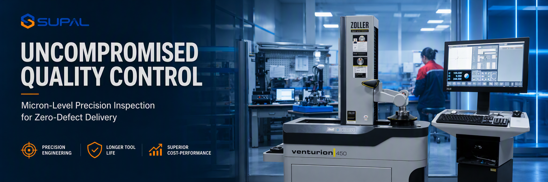
Supal (Changzhou) Precision Tools Co., Ltd.is al vele jaren bezig met het ontwerpen, produceren en verkopen van gereedschappen van massief karbide met een totale investering van meer dan 10 miljoen en bestaat uit een groep ervaren werknemers.Als professionele gereedschapsfabrikant is het een van de directeuren van Changzhou Xiaxiashu Tools Association.ANCA van Australië en NC-snijmachines met vijf assenBovendien is het bedrijf uitgerust met een automatische detector van ZOLLER en een ultraprecie...
Leer meer

0

Gevestigd jaar:

0

Miljoen+
Werknemers

0

Miljoen+
Jaarlijkse Verkoop:
CHINA Supal (Changzhou) Precision Tools Co.,Ltd Hoge kwaliteit
Vertrouwenszegel, kredietcontrole, RoSH en beoordeling van de leverancierscapaciteit. Het bedrijf heeft een strikt kwaliteitscontrolesysteem en een professioneel testlaboratorium.
CHINA Supal (Changzhou) Precision Tools Co.,Ltd Ontwikkeling
Interne professionele ontwerpteam en geavanceerde machineworkshop. We kunnen samenwerken om de producten te ontwikkelen die je nodig hebt.
CHINA Supal (Changzhou) Precision Tools Co.,Ltd Vervaardiging
Geavanceerde automatische machines, strikt procesbesturingssysteem. We kunnen alle elektrische terminals maken die u niet nodig heeft.
CHINA Supal (Changzhou) Precision Tools Co.,Ltd 100% dienstverlening
Bulk en op maat gemaakte kleine verpakkingen, FOB, CIF, DDU en DDP. Laat ons u helpen de beste oplossing te vinden voor al uw zorgen.

kwaliteit Carbide freesgereedschap & vierkante molens fabrikant

Vind Producten die beter aan Uw Vereisten voldoen.
Gevallen & Nieuws
De laatste hotspots.
How to Set Cutting Parameters and Geometry for Reliable Deep-Hole Carbide Drilling
How to Set Cutting Parameters and Geometry for Reliable Deep-Hole Carbide Drilling Deep-hole drilling is often treated as a routine operation, but it fails more often than shallow drilling because small errors accumulate over a long, unsupported length of cut. Chip evacuation, coolant delivery, hole straightness, and heat management become critical once the depth-to-diameter ratio increases. A drill that performs well in a shallow hole can walk off-center, deflect, overheat, or break when the same geometry is pushed into a deep bore without adjustment. Carbide drills give CNC machinists, process engineers, and purchasing teams a way to hold tight tolerances and achieve longer, more predictable tool life in demanding materials. Realizing that potential depends on selecting the correct point geometry, flute design, and coolant strategy, then building a parameter approach that keeps the chip formation and evacuation stable as the hole gets deeper. This guide explains how to think through deep-hole carbide drilling from geometry selection to a controlled parameter-adjustment sequence, without relying on a single universal number for every job. Why Deep Holes Behave Differently From Shallow Ones As the depth-to-diameter (L/D) ratio increases, several conditions change simultaneously. Chip evacuation becomes the limiting factor In a shallow hole, chips can exit quickly. In a deep hole, chips must travel a longer distance along the flutes before reaching the surface. If the chip cannot escape efficiently, it packs inside the flute, increases torque, and can jam the drill or cause it to break. Rigidity and deflection increase A longer, unsupported drill body is more prone to deflection under radial force. Deflection can cause the hole to drift off the intended axis, produce an oversized or tapered bore, or increase load on one side of the cutting edge. Heat accumulates near the tip Heat generated at the cutting edge has a longer path to dissipate through the tool and chips. Without adequate coolant delivery to the tip, temperature can rise enough to accelerate wear, promote built-up edge, or damage the coating. Entry conditions affect the entire hole A poor entry — including an inaccurate starting point, excessive initial engagement, or unstable initial contact — can set the drill on an incorrect path that becomes difficult to correct as depth increases. Choose a Point Geometry Suited to the Application The point geometry determines how the drill initiates the cut, centers itself, and forms the initial chip. Self-centering points A point designed for self-centering behavior reduces the tendency to walk at entry, which is especially valuable when drilling without a pilot hole or spot drill. This is often beneficial on curved, angled, or interrupted surfaces where an inaccurate starting point can be magnified over a long hole depth. Split-point and multi-facet designs Split-point or multi-facet grinds can improve self-centering and reduce thrust force compared with a conventional conical point. The correct choice depends on the material, entry surface condition, and whether the operation uses a pilot hole. Point angle A more acute point angle generally suits softer, more ductile materials and can reduce thrust force, while a more obtuse angle is often selected for harder or more abrasive materials to support the cutting edge. The exact angle should follow the tool supplier's recommendation for the specific material group rather than a single fixed number applied to every job. Flute Design and Chip Evacuation Flute geometry and helix Flute geometry controls how efficiently chips move along the drill body. A helix suited to the application helps guide chips out consistently. If the flute cross-section is too small for the chip volume being generated, evacuation slows down and chips can pack, especially as the hole gets deeper. Web thickness and rigidity The web (the central core of the drill) affects both rigidity and chip space. A thicker web increases strength and resistance to deflection but reduces the volume available for chip flow. Selecting the correct balance depends on the depth-to-diameter ratio, material, and whether the operation prioritizes straightness or maximum feed rate. Margin and bearing surface The margin supports the drill against the hole wall and helps maintain straightness. Excessive margin contact can increase friction and heat, while insufficient support can allow the drill to wander. The design should match the expected depth and material hardness. Coolant Delivery Is Not Optional in Deep Holes For most deep-hole applications, especially beyond a moderate L/D ratio, coolant-through drilling is strongly preferred over external coolant alone. External coolant may not reach the cutting edge once the drill is several diameters deep, leaving the tip to run hot and dry. Key considerations for coolant delivery: Confirm that coolant pressure and flow are sufficient to reach the tip and flush chips back along the flutes at the intended depth. Verify that the coolant channels in the holder, adapter, and drill are aligned and unobstructed. Match coolant type and concentration to the material and drill coating, following the tool and coolant supplier's guidance. Inspect for blocked or undersized coolant passages if evacuation problems appear only after switching tools or holders. If coolant-through capability is not available on the machine, the drilling strategy, depth per pass, and expected productivity should be adjusted accordingly, since dry or externally cooled deep-hole drilling carries a higher risk of chip packing and heat buildup. Peck Drilling and Depth-Management Strategy Peck drilling — periodically retracting the drill to clear chips — is a common strategy for managing evacuation in deep holes, particularly when coolant-through capability is limited or the material produces long, stringy chips. When peck drilling helps Peck cycles are useful when: The material generates continuous or difficult-to-break chips Coolant-through pressure is marginal for the depth and diameter The application has a history of chip packing or tool breakage at a specific depth The hole depth significantly exceeds the drill's typical continuous-drilling capability Trade-offs to consider Frequent retraction can reduce productivity and, in some cases, introduce additional entry-like conditions each time the drill re-engages, which may affect surface finish or increase wear at the point. The retraction distance and pecking depth should be tuned to clear chips effectively without unnecessary cycles. When coolant-through delivery is strong and reliable, some operations can run continuously or with fewer pecks, but this should be validated for the specific tool, material, and machine rather than assumed. Building a Parameter Strategy for Deep-Hole Drilling Cutting speed, feed rate, and peck strategy should always start from the tool supplier's data for the exact drill diameter, coating, and material group. Treat published values as a starting reference, then validate them on the actual machine, holder, workpiece material, and hole depth. Sequence for establishing a deep-hole drilling process Confirm tool and hole specification. Diameter, target depth, tolerance, and surface finish requirements. Select geometry. Point style, flute design, and coating suited to the material and depth-to-diameter ratio. Verify coolant delivery. Confirm coolant-through capability, pressure, and alignment before running the program. Set an initial speed and feed. Use the supplier's starting range for the diameter and material. Choose a peck strategy if needed. Based on chip form, coolant capability, and depth. Run a test hole and inspect. Check chip form, sound, spindle load trend, hole straightness, and surface finish. Adjust one variable at a time. Modify feed, peck depth, or coolant before changing speed, and record the result. Confirm consistency over multiple holes. A single successful hole does not guarantee a stable process; verify repeatability across a small batch before finalizing parameters. If the drill is walking or drifting Review the entry method, point geometry, initial engagement, and whether a pilot hole or spot drill is needed. Confirm that the workpiece surface at the entry point is suitable for the chosen point style. If chips are packing or torque is rising Check coolant pressure and alignment first, then flute design and web thickness relative to the material's chip characteristics. Consider introducing or adjusting peck drilling. If the tool is overheating or wearing quickly Verify coolant reaches the tip at the actual depth, confirm the coating is suited to the material and cutting temperature, and review whether cutting speed is appropriate for the material and diameter. If holes are oversized, tapered, or angled Investigate deflection sources: tool overhang, rigidity of the workholding, runout, and whether the feed or engagement is too aggressive for the drill's rigidity at that depth. Common Mistakes in Deep-Hole Drilling Using a shallow-hole parameter set for a deep hole Parameters validated for a short hole may not evacuate chips effectively once depth increases. Revalidate speed, feed, and peck strategy for the actual L/D ratio. Relying on external coolant alone at high depth External coolant often cannot reach the cutting edge once the drill is several diameters into the material. This can cause heat buildup and chip packing that are difficult to diagnose without checking coolant delivery first. Ignoring entry conditions An unstable or inaccurate entry can set the drill on an incorrect path that worsens with depth. Address point geometry and entry method before increasing speed or feed. Changing multiple parameters at once When troubleshooting a failure, changing several variables together makes it difficult to identify the actual cause. Adjust one factor, test, and record the outcome before making further changes. Assuming one drill design fits every depth and material Point angle, flute geometry, web thickness, and coating should be matched to the specific combination of material, depth, and required tolerance rather than reused from an unrelated application. Frequently Asked Questions Is coolant-through drilling always necessary for deep holes? It is strongly recommended once the depth-to-diameter ratio increases beyond a moderate range, because external coolant often cannot reach the tip. The exact threshold depends on the material, drill design, and machine capability, and should be confirmed with the tool supplier. How do I know if I need peck drilling? Peck drilling is generally useful when chips are not evacuating cleanly with continuous drilling, especially in materials that produce long or stringy chips, or when coolant-through pressure is limited. Test both continuous and pecked strategies on the actual setup to compare chip evacuation and tool condition. What causes a carbide drill to break in a deep hole? Common causes include chip packing from insufficient evacuation, excessive deflection from tool overhang or poor rigidity, inadequate coolant reaching the cutting edge, and using parameters or geometry not suited to the depth and material. Can the same drill be used for different materials? A drill designed for one material group may not perform well in another due to differences in chip formation, hardness, and thermal behavior. Confirm the drill's intended material range and coating before applying it to a new application. What information should I send to a tool supplier for a deep-hole drilling application? Provide the material grade and hardness, target hole diameter and depth, tolerance and surface finish requirements, whether coolant-through capability is available, current parameters if applicable, and photographs of chip form or tool wear from previous attempts. Conclusion Reliable deep-hole carbide drilling depends on matching point geometry, flute design, and coolant strategy to the material and depth-to-diameter ratio, then validating cutting parameters through a controlled, one-variable-at-a-time process. Chip evacuation and coolant delivery to the cutting edge are usually the deciding factors between a stable process and repeated tool failure. Supal (Changzhou) Precision Tools Co., Ltd. supplies carbide drills, reamers, and customized cutting solutions for demanding CNC applications. To evaluate a deep-hole drilling process, contact Supal with your material grade, target hole diameter and depth, tolerance requirements, coolant-through availability, and any photographs of chip form or tool wear from prior attempts. This information helps identify a suitable tool geometry and a practical starting strategy for on-machine validation.

2026

08/04

How to Choose a Carbide End Mill for 304 and 316 Stainless Steel
How to Choose a Carbide End Mill for 304 and 316 Stainless Steel 304 and 316 stainless steels are widely used because of their corrosion resistance, toughness, and formability. Those same properties make them challenging to mill. Both materials can generate high cutting pressure, retain heat near the cutting edge, adhere to the tool, and work-harden when the edge rubs instead of cutting. The correct carbide end mill must do more than resist wear. It must shear the material cleanly, evacuate chips before they are recut, maintain edge strength under an interrupted milling load, and control vibration. Flute count, helix angle, rake geometry, carbide grade, edge preparation, coating, corner design, tool reach, coolant delivery, and toolpath all influence the result. This guide explains how CNC machinists, process engineers, and purchasing teams can select an end mill for 304 and 316 stainless steel and establish a controlled starting process for validation on the actual machine. Why 304 and 316 Stainless Steel Are Difficult to Mill 304 and 316 are austenitic stainless steels. They are generally tougher and more ductile than common carbon steels. Instead of forming a brittle, easily separated chip, the material can deform significantly before it shears. Four characteristics are especially important. Work hardening When a cutting edge rubs, dwells, or takes an excessively thin chip, the surface can harden. The next flute must then cut through material that is harder than the original workpiece. This raises force and accelerates wear or chipping. Repeated spring passes with insufficient stock can make the problem worse. Low thermal conductivity Heat does not move away through the workpiece as quickly as it does in many ordinary steels. More heat remains in the chip and cutting zone. The tool coating, coolant strategy, and engagement must therefore be selected to manage localized temperature. Adhesion and built-up edge Stainless steel can adhere to the rake face and cutting edge. The deposit changes the effective geometry, increases force, and may pull small fragments from the carbide when it breaks away. A sharp but supported edge, suitable coating, and consistent chip thickness help control adhesion. Tough, difficult-to-evacuate chips Long or curled chips can remain in slots and pockets. Recutting damages the surface and creates unpredictable impact loads. Tool flute volume and coolant direction are therefore as important as theoretical feed capacity. 304 vs. 316: What Changes for Tool Selection? Both grades require a stainless-steel-oriented tool, but 316 often demands a more conservative process. Its alloy content and corrosion-resistant composition can increase cutting difficulty, depending on material condition and supplier specification. Treat the exact grade, condition, hardness, casting or wrought form, and stock surface as process inputs rather than assuming that every bar marked "304" or "316" machines identically. For 316, prioritize stable edge strength, heat control, consistent chip formation, and reliable coolant access. When moving a proven 304 process to 316, do not automatically reuse every parameter. Begin from the tool supplier's applicable range, assess spindle load and edge condition, and validate one change at a time. Choose the Correct Flute Count A four-flute end mill is a common starting point for stainless steel because it balances core strength, feed capacity, and chip space. However, the operation determines whether four flutes are appropriate. Slotting and deep pockets Full-width slotting generates a large chip volume and keeps more of the tool engaged. A lower flute count or a tool with enlarged gullets may improve evacuation. If the flutes pack, adding more cutting edges will not improve productivity. Side milling and adaptive roughing With controlled radial engagement, a four- or five-flute design may offer greater feed capacity and good core strength. The toolpath must maintain a predictable engagement angle and provide a clear chip exit. Finishing Additional flutes can support a higher table feed in light radial engagement, but only when runout is controlled and each flute shares the cut. For critical finishes, use a consistent stock allowance and avoid finishing with an edge damaged during roughing. Explore Supal's end mills for stainless steel when comparing flute configurations, coatings, and cutting lengths. Helix, Pitch, Rake, and Core Design Helix angle A higher helix can reduce radial cutting force and promote smoother shearing, which is useful in stainless steel. It also changes axial force, so workholding and thin-wall stability must be considered. A moderate-to-high helix is often selected for stainless applications, but the correct value depends on tool diameter, reach, flute count, and operation. Variable helix and variable pitch Unequal helix or pitch spacing can disrupt periodic cutting forces and reduce the tendency toward chatter. This is valuable with long reach, less-rigid workholding, or higher axial engagement. Variable geometry is not a substitute for correcting excessive runout, loose fixtures, or unnecessary overhang. Positive rake with edge support A positive rake reduces cutting pressure and helps the tool shear rather than plough. The cutting edge must still be strong enough for stainless steel. An edge that is extremely sharp but unsupported may micro-chip, while an overly honed edge may rub and promote work hardening. Core diameter and flute volume A thicker core increases rigidity and fracture resistance but reduces gullet space. The tool designer must balance stiffness against chip evacuation. Deep slots need more flute volume than light side milling. Select the Coating for Heat and Adhesion Control Coating selection should match the operation and cutting temperature. Common stainless-steel applications use heat-resistant PVD coatings such as AlTiN-, TiAlN-, AlCrN-, or other application-specific multilayer systems. Actual performance depends on coating composition, thickness, adhesion, edge preparation, substrate, and process conditions鈥攏ot color or marketing name alone. A suitable coating should: Reduce friction and material adhesion Protect the carbide from localized heat Maintain hardness at the intended cutting temperature Remain securely bonded under intermittent milling loads Preserve an edge geometry appropriate for the operation Do not use coating to compensate for a poor chip path or incorrect geometry. If chips remain in the slot, even a heat-resistant coating can fail through recutting and impact. For wet machining, deliver coolant consistently. Repeated uncontrolled heating and cooling can stress the edge. For dry or air-assisted strategies, confirm that the tool, coating, material, and engagement are intended for that thermal condition. Square Corner or Corner Radius? A square end mill produces a sharp internal corner but concentrates stress at the tool corner. Heavy engagement, sudden entry, or chatter can cause corner chipping. If the part permits a radius, a corner-radius end mill can strengthen the most vulnerable region and distribute the load. It is often useful for roughing, semi-finishing, and high-engagement stainless operations. Supal's corner radius end mills offer options when edge strength is more important than a perfectly sharp internal corner. The radius must still match the programmed path and part geometry. Do not allow the tool radius to interfere with an internal fillet or leave unexpected stock. Minimize Reach and Control Runout Use the shortest practical flute length and tool projection. Stainless steel generates high cutting forces, and excessive reach increases deflection. Deflection changes chip thickness, causes taper, and may overload the tool as it springs back into the workpiece. Runout is equally important. If one flute projects farther, it carries more load while the others rub. The overloaded flute may chip, and the rubbing flutes generate heat and work hardening. Before changing the tool grade or parameters: Clean the tool shank, holder, collet, nut, and spindle interface. Inspect the holder and collet for wear or damage. Measure runout near the cutting edge using the shop's normal procedure. Use the shortest holder and projection compatible with the feature. Confirm that the workpiece and fixture cannot move under cutting load. If a standard tool requires excessive flute length or neck clearance, a custom milling tool may provide a better balance of reach, core strength, and chip space. Build a Parameter Strategy That Avoids Rubbing Numerical cutting data must come from the supplier for the exact tool and material group. Treat it as a starting range, then validate on the actual machine, holder, fixture, coolant system, material condition, and toolpath. The process should maintain a real chip load. If feed per tooth is too low, the edge may rub against a work-hardened surface instead of cutting beneath it. If chip load or engagement is too high, the edge can overload or deflect. Use this adjustment sequence: Confirm material and operation. Verify 304 or 316, hardness or condition, stock surface, slotting versus side milling, and required reach. Select tool geometry. Match flute count, helix, pitch, coating, corner, and cutting length to the operation. Set engagement. Avoid unnecessary full-width cutting. Use a controlled radial engagement where the part allows it. Calculate spindle speed and feed. Use the supplier's range for the actual diameter and flute count. Confirm chip formation. Chips should be formed consistently and removed without packing or discoloration that indicates excessive heat. Monitor spindle load and sound. Look for stable trends rather than isolated values. Inspect the edge early. Check for adhesion, notching, flank wear, or micro-chipping before catastrophic failure. Change one variable at a time. Record the result for future jobs. When radial engagement becomes very small, actual chip thickness may be lower than the programmed feed-per-tooth value suggests. Any compensation should follow the tool supplier's guidance and be validated carefully. Toolpath and Coolant Recommendations Adaptive or constant-engagement roughing can reduce sudden load changes and limit the time each edge remains in contact. Avoid driving the tool into an internal corner where engagement rises sharply. Use a suitable ramp, helix, or predrilled entry rather than an unsupported plunge. Coolant should reach the active cutting edge and carry chips toward an open exit. In deep pockets, one nozzle aimed at the shank may be ineffective. Verify nozzle position at the actual depth and consider multiple directions when the cavity traps chips. For finishing, remove loose chips before the final pass. Leave a consistent allowance and use a stable entry and exit. A separate finishing tool may improve process control for critical surfaces. Troubleshooting Common Failure Modes Rapid flank wear Check cutting speed, coating suitability, coolant consistency, material hardness, and whether the tool is rubbing. Uniform wear on all flutes suggests a different mechanism from damage concentrated on one flute. Built-up edge Review rake geometry, coating, chip load, coolant or lubrication, and cutting temperature. Do not automatically reduce feed; an excessively light chip can increase rubbing and adhesion. Corner chipping Check runout, entry method, internal-corner engagement, tool projection, and whether a corner radius is permitted. Inspect for chip recutting and chatter. Notching at the depth-of-cut line Look for scale, a hardened surface, repeated axial engagement at one location, and unsuitable edge preparation. Varying axial depth may distribute wear, but the underlying material and process conditions must still be corrected. Chatter and unstable finish Reduce unnecessary reach, strengthen workholding, verify runout, and review engagement. A variable-pitch tool can help after basic rigidity problems have been corrected. Common Selection Mistakes Buying by coating color Similar colors do not guarantee the same coating composition or performance. Specify the workpiece, operation, engagement, coolant, and failure mode. Choosing the highest flute count More flutes reduce chip space. The correct number depends on slotting, side milling, depth, material, and evacuation. Using an aluminum geometry for stainless steel A very sharp, open aluminum geometry may lack the edge support and coating needed for stainless steel. Match rake, core, and edge preparation to the material. Copying a 304 process directly to 316 The same tool may be suitable, but parameters and edge life should be revalidated for the exact 316 condition and setup. Using excessive tool length Long projection creates deflection and uneven chip load. Select the shortest practical tool or a purpose-designed neck. Frequently Asked Questions Is a four-flute end mill always best for 304 stainless steel? No. Four flutes are a common starting point, but deep slots may need more chip space, while light side milling may support additional flutes. Choose according to engagement and evacuation. Can the same end mill machine 304 and 316? Often it can, provided the geometry and coating are suitable. However, the cutting data and expected life must be validated for each grade, material condition, machine, and operation. Should stainless steel be milled with coolant? Many applications benefit from consistent coolant for heat and chip control. The correct strategy depends on the tool, coating, machine, operation, and material. Avoid an inconsistent thermal condition. Why does the tool chip when the programmed feed is low? Low feed can cause rubbing and work hardening. Chipping may also result from runout, chatter, excessive reach, chip recutting, sudden engagement, or an unsupported edge. What information should I send to the tool supplier? Provide the exact stainless grade and condition, hardness if known, operation, feature dimensions, tool diameter and reach, holder, measured runout, coolant method, current cutting data, toolpath, required finish, and photographs of tool wear and chips. Conclusion Selecting an end mill for 304 or 316 stainless steel requires a balance of sharp cutting action, edge support, heat resistance, rigidity, and chip evacuation. A stainless-specific carbide substrate and coating are only part of the solution. Flute count, variable geometry, corner design, runout, projection, coolant direction, and toolpath must work together. Start with supplier data for the exact tool, maintain a meaningful chip load, avoid unnecessary full-width engagement, and inspect the edge before normal wear develops into chipping. Validate every numerical setting on the actual machine and material condition. Supal (Changzhou) Precision Tools Co., Ltd. supplies carbide end mills and customized cutting solutions for stainless steel machining. To discuss a 304 or 316 application, contact Supal with the material grade, feature drawing, tool size, machine and holder details, coolant method, current cutting data, and photographs of the used edge. This information helps establish a suitable tool geometry and controlled starting process for on-machine validation.

2026

07/31

Carbide End Mill Chipping vs. Normale slijtage: een praktische handleiding voor de diagnose van storingen
Carbide Freesbeitels: Spaanders versus Normale Slijtage: Een Praktische Gids voor Foutdiagnose Een carbide freesbeitel is een verbruiksartikel, maar niet elke beschadigde snede is normale slijtage. Uniforme flankenslijtage is een voorspelbaar gevolg van het verspanen. Spaanders, microbreuken, hoekbreuken en plotseling falen van het gereedschap geven aan dat de snede is blootgesteld aan mechanische of thermische belastingen die verder gaan dan wat het gereedschap en de opstelling kunnen verdragen. Het verschil is belangrijk. Als normale slijtage wordt aangezien voor spaanders, kan een werkplaats onnodig parameters verlagen en productiviteit verliezen. Als spaanders worden behandeld als normale slijtage, kan het proces doorgaan totdat het gereedschap breekt, het werkstuk wordt afgekeurd, of de spil en de werkstukopname worden blootgesteld aan een zware belasting. Een betrouwbare diagnose begint met de locatie en het patroon van de schade. Ingenieurs moeten onderzoeken welke snijkant is aangetast, waar de schade begint, of alle snijkanten dezelfde slijtage vertonen, en wat er is veranderd in het geluid, de spilbelasting, de spanen, de oppervlakteafwerking en de afmetingen vóór het falen. Deze gids presenteert een praktische methode om normale carbide slijtage te onderscheiden van mechanische spaanders en om elk patroon te koppelen aan waarschijnlijke oorzaken in het gereedschap, de houder, de machine, het gereedschapspad, de koelstrategie en de snijparameters. Hoe Normale Slijtage van Freesbeitels Eruitziet Normale slijtage ontwikkelt zich over het algemeen geleidelijk en relatief consistent over de snijkanten die de belasting delen. Onder vergroting kan de flank achter de snijkant een smalle versleten band vertonen. De snijkant wordt minder scherp, de snijkrachten nemen langzaam toe en de oppervlakteafwerking of dimensionale nauwkeurigheid verandert in een herhaalbare richting. Typische indicatoren zijn: Een continue slijtageband langs de actieve snijlengte Vergelijkbare slijtage op alle snijkanten wanneer de slag nauwkeurig is gecontroleerd Geleidelijke in plaats van plotselinge toename van de spilbelasting Voorspelbare afname van de oppervlaktekwaliteit Stabiele spanen zonder tekenen van zware impact of ophoping Dimensionale drift die zich over meerdere werkstukken voortzet Slijtage van de coating geconcentreerd in de actieve snijzone Normale slijtage betekent niet dat het gereedschap moet worden gebruikt totdat het faalt. Een proces moet een vervangingspunt definiëren op basis van dimensionale controle, oppervlakteafwerking, staat van de snijkant, spilbelasting of een bewezen aantal werkstukken. Het doel is om het gereedschap te vervangen tijdens voorspelbare slijtage, voordat de snijkant voldoende sterkte verliest om te beginnen met spaanderen. Hoe Mechanische Spaanders Verschillen Spaanders verwijderen kleine of grote fragmenten van de snijkant. De breuk kan beperkt zijn tot de hoek, verschijnen als micro-inkepingen langs de snijkant, of zich uitbreiden tot een grote breuk. In tegenstelling tot uniforme flankenslijtage, zijn spaanders vaak onregelmatig. Veelvoorkomende tekenen zijn: Eén snijkant is zwaarder beschadigd dan de andere De hoek breekt terwijl de resterende snijlengte relatief scherp lijkt Kleine inkepingen verschijnen nabij de snijdiepte De snijkant heeft een gekarteld profiel in plaats van een gladde slijtageband Het snijgeluid verandert plotseling De spilbelasting vertoont intermitterende pieken Het afgewerkte oppervlak bevat willekeurige krassen, stappen of herhalende markeringen van de beschadigde snijkant De levensduur van het gereedschap varieert sterk tussen nominaal identieke opstellingen Spaanders worden meestal geassocieerd met impact, ongelijke belasting, onvoldoende ondersteuning van de snijkant, trillingen, heropname van spanen, onderbroken verspaning, overmatige doorbuiging of thermische schok. Verschillende oorzaken kunnen samen voorkomen. Lees de Schade Locatie Voordat U Parameters Wijzigt Spaanders op slechts één snijkant Wanneer één snijkant eerder faalt dan de andere, controleer dan eerst de slag en de klemming. Een gereedschap met radiale slag verdeelt de spanenlast niet gelijkmatig. De hoge snijkant verwijdert een grotere spaander, terwijl de andere snijkanten kunnen wrijven. Deze combinatie verhoogt de kracht, warmte en snijkantspanning. Reinig de houder, de spantang, de moer, de schacht van het gereedschap en de spilinterface volgens de onderhoudsprocedure van de werkplaats. Meet de slag dicht bij de snijkant, niet alleen aan de schacht. Inspecteer de spantang en de houder op slijtage, vervuiling of schade. Het vervangen van de freesbeitel zonder de oorzaak te corrigeren, kan dezelfde fout reproduceren. Hoekspaanders De hoek van een vierkante freesbeitel is een spanningsconcentratie. Het wordt tegelijkertijd blootgesteld aan radiale en axiale krachten en kan kwetsbaar zijn tijdens het inrijden, uitrijden, scherpe richtingsveranderingen en zware belasting. Als het onderdeelontwerp dit toelaat, kan een hoekradiusgeometrie meer ondersteuning van de snijkant bieden dan een scherpe vierkante hoek. Supal's hoekradius freesbeitels bieden opties voor processen waarbij hoeksterkte en stabiele levensduur van de snijkant belangrijker zijn dan het produceren van een perfect scherpe interne hoek. Hoekspaanders kunnen ook duiden op overmatige radiale belasting, een agressieve inrijding, onvoldoende nabewerkingstoeslag, of een gereedschapspad dat de snijder met een plotselinge toename van de belasting in een hoek stuurt. Inkepingen op de snijdiepte-lijn Een gelokaliseerde inkeping waar de snijkant herhaaldelijk het werkstuk binnendringt, kan het gevolg zijn van een geconcentreerde mechanische en thermische belasting. Schaal, een geharde oppervlakte laag, werkverharding, onderbroken materiaal, of herhaaldelijk verspanen op één axiale positie kunnen bijdragen. Het veranderen van de axiale diepte kan de slijtage over een ander deel van de snijkant verdelen, maar dit moet worden geëvalueerd samen met de staat van het werkstuk, de coating, de voorbereiding van de snijkant, de koelvloeistof en het gereedschapspad. Het simpelweg verplaatsen van de slijtageband corrigeert geen ongeschikt gereedschap of instabiel proces. Spaanders langs meerdere snijkanten Schade over meerdere snijkanten wijst op een probleem op systeemniveau: trillingen, heropname van spanen, overmatige belasting, een te zwakke snijkant voor de bewerking, of ongeschikte snijgegevens. Inspecteer de holte op vastgelopen spanen en vergelijk het schade patroon met de oppervlaktemarkeringen. Willekeurige snijkantschade en willekeurige krassen duiden vaak op heropname, terwijl regelmatige golven op trillingen wijzen. Volledige breuk nabij de snijkant of de hals Een grote breuk kan volgen op een zware overbelasting, botsing, overmatige gereedschapsprojectie, zwakke dwarsdoorsnede, of opgebouwde microbreuken. Gereedschappen met een kleine diameter zijn bijzonder gevoelig voor slag, hantering, kwaliteit van de houder en plotselinge veranderingen in belasting. Controleer het programma, de houder, het bereik van het gereedschap en de werkelijke speling van het onderdeel voordat u de kwaliteit van het carbide de schuld geeft. Voor toepassingen met zeer kleine diameters, bekijk Supal's micro freesbeitels en definieer de opstelling rond minimale slag, korte projectie, gecontroleerde inrijding en betrouwbare spaanafvoer. Scheid Spaanders van Trillingen Trillingen zijn zelf-opgewekte trillingen binnen het gereedschap-machine-werkstuk systeem. Het kan leiden tot spaanders, maar niet elke beschadigde tool is het gevolg van trillingen. Bewijs van trillingen kan omvatten: Herhalende golven of gelijkmatig verdeelde markeringen op het werkstuk Een sterk tonale geluid in plaats van willekeurige impacts Schade op vergelijkbare posities rond meerdere snijkanten Instabiliteit die verandert wanneer de spilsnelheid wordt aangepast Verhoogde gevoeligheid met langere gereedschapsprojectie of zwakkere werkstukopname Verminder eerst onnodige overhang en bevestig de klemming van het werkstuk. Controleer de staat van de houder en de slag. Controleer de radiale belasting, de axiale belasting en de inrijdcondities. Een variabele spoed of variabele spoedhoek gereedschap kan helpen periodieke krachten te verstoren, maar geometrie kan geen losse armatuur, overmatige reikwijdte of een houder met onacceptabele slag compenseren. Vermijd het wijzigen van meerdere parameters tegelijk. Een gecontroleerde aanpassing van de spilsnelheid kan helpen een stabiliteitsprobleem te identificeren, terwijl een verlaging van de voedingssnelheid alleen kan leiden tot wrijving en warmte zonder de oorzaak van de trilling te elimineren. Gereedschapsgeometrie en Substraat Moeten Passen bij het Faalpatroon Een harder gereedschap is niet automatisch een taaier gereedschap. Carbide kwaliteit, korrelstructuur, kobaltgehalte, voorbereiding van de snijkant, kerndiameter, spoedhoek, spaanhoek, aantal snijkanten, coating en hoekontwerp beïnvloeden allemaal de balans tussen slijtvastheid en breukweerstand. Een scherpe snijkant vermindert de snijkracht, maar heeft minder materiaal dat deze ondersteunt. Een geslepen of beschermde snijkant kan impact weerstaan, maar kan de kracht verhogen in een bewerking die zeer lage snijdruk vereist. Meer snijkanten kunnen de potentiële voedingscapaciteit verhogen, maar verminderen de spaanderruimte. Een dikkere kern verbetert de stijfheid, maar verandert ook het volume van de snijkant. Als een standaard gereedschap herhaaldelijk faalt omdat de reikwijdte, de hals, de lengte van de snijkant of de hoekgeometrie ongeschikt is, kan een custom freesbeitel de geometrie in balans brengen rond het werkelijke onderdeel in plaats van een generiek gereedschap in de toepassing te forceren. Een Gecontroleerde Probleemoplossingsreeks Wanneer er spaanders optreden, documenteer dan het defecte gereedschap voordat u het weggooit. Markeer de snijkantnummers, fotografeer de snijkant onder consistente vergroting en noteer het aantal werkstukken, de spilbelasting, het geluid, de staat van het oppervlak en de programma-locatie. Los vervolgens het probleem op in deze volgorde: Bevestig dat er geen botsing of programmeerfout was. Controleer snelle bewegingen, inrijden, terugtrekken, resterend materiaal, speling van de armatuur en onverwacht resterend materiaal. Inspecteer de slag en het houder systeem. Reinig interfaces, meet nabij de snijkant en vergelijk de schade tussen de snijkanten. Verminder de gereedschapsprojectie. Gebruik de kortst mogelijke overhang en snijlengte. Verifieer de werkstukopname. Controleer de ondersteuning van het werkstuk, de stijfheid van de armatuur en of dunne wanden bewegen tijdens het verspanen. Onderzoek de spaanafvoer. Zoek naar vastgelopen of heropgenomen spanen, vooral in sleuven en diepe holtes. Controleer de veranderingen in belasting. Identificeer hoeken, inrijdingen, uitrijdingen en onderbroken gebieden waar de belasting plotseling toeneemt. Controleer de gereedschapsgeometrie. Controleer of het aantal snijkanten, het hoekontwerp, de voorbereiding van de snijkant, de coating en de reikwijdte overeenkomen met de bewerking. Controleer de snijgegevens. Gebruik het bereik van de leverancier als referentie en pas één variabele tegelijk aan. Voer een gecontroleerde vergelijking uit. Houd materiaal, houder, gereedschapsprojectie en gereedschapspad constant terwijl u de geselecteerde wijziging evalueert. De uiteindelijke parameters moeten worden gevalideerd op de specifieke machine, houder, armatuur, werkstukkwaliteit en koelsysteem. Een numerieke instelling die van een andere machine is gekopieerd, mag niet worden beschouwd als een gegarandeerde oplossing. Parameter Aanpassingen per Symptoom Spaanders tijdens het inrijden Controleer of de freesbeitel de geprogrammeerde duik- of hellingsbeweging ondersteunt. Verminder plotselinge belasting, gebruik een geschikte helling of spiraalvormige inrijding, of boor voor wanneer dit van toepassing is. Verifieer dat het gereedschap center-snijdend is als het programma dit vereist. Spaanders in interne hoeken De belastinghoek neemt scherp toe in hoeken. Gebruik een gereedschapspad dat de belasting controleert, resterend materiaal in de hoek vermindert en abrupte richtingsveranderingen vermijdt. Een kleinere radiale belasting met een consistent pad kan stabieler zijn dan een conventionele volledige breedte draai. Spaanders na een lange stabiele snede Zoek naar opgebouwde warmte, progressieve slijtage, coatingverlies, spaanderophoping en een slijtagegrens die is overschreden. Het gereedschap kan beginnen met normale slijtage en vervolgens voldoende sterkte van de snijkant verliezen om te breken. Het instellen van een eerder vervangingspunt kan effectiever zijn dan het verlagen van het hele proces. Spaanders met opgebouwde rand Aangehecht materiaal kan herhaaldelijk afbreken en aan de carbide snijkant trekken. Controleer werkstukspecifieke geometrie, coating of snijkant polijsten, smering, spaandikte en koelvloeistofrichting. Corrigeer het aanhechtingsmechanisme in plaats van alleen de voedingssnelheid te verlagen. Spaanders met lange gereedschapsprojectie Verminder de projectie waar mogelijk, gebruik een gereedschap met een hals ontworpen voor het onderdeel, versterk de werkstukopname en pas een gereedschapspad toe met gecontroleerde radiale belasting. Het verlagen van de snijkracht kan helpen, maar overmatige projectie blijft een structurele beperking. Veelvoorkomende Diagnostische Fouten Eerst de carbide kwaliteit de schuld geven Materiaalkwaliteit is belangrijk, maar slag, houdervervuiling, gereedschapspad overbelasting en heropname van spanen zijn meer voorkomende procesvariabelen. Verifieer het systeem voordat u het substraat verandert. Voedingssnelheid verlagen zonder de spaandikte te controleren Een te lage voedingssnelheid kan leiden tot wrijving, warmte en instabiele snijkantbelasting. Elke aanpassing moet binnen een praktisch snijbereik voor het exacte gereedschap en materiaal blijven. Alleen het gebroken gereedschap inspecteren Het werkstukoppervlak, de spaandikte, de houder, de spantang, de armatuur, het spilbelastingsrecord en de programma-locatie bevatten essentiële bewijzen. Schade aan het gereedschap alleen bewijst zelden de hoofdoorzaak. Gereedschap, coating, snelheid, voeding en koelvloeistof tegelijkertijd wijzigen Meerdere gelijktijdige wijzigingen kunnen een beter resultaat opleveren zonder te onthullen waarom. Wijzig één gecontroleerde factor tegelijk wanneer de productieomstandigheden dit toelaten. Alle snijkantverlies als dezelfde fout behandelen Hoekspaanders, inkepingen op snijdiepte, overbelasting van één snijkant, micro-spaanders op meerdere snijkanten en volledige breuk van de hals wijzen op verschillende mechanismen. Noteer de exacte locatie en het patroon. Veelgestelde Vragen Wordt een beschadigde carbide freesbeitel altijd veroorzaakt door een te hoge voedingssnelheid? Nee. Overmatige spaandikte kan overbelasting veroorzaken, maar spaanders kunnen ook het gevolg zijn van slag, trillingen, heropname van spanen, lange overhang, zwakke werkstukopname, plotselinge belasting, ongeschikte geometrie, aanhechting of thermische effecten. Hoe kan ik zien of slag de oorzaak is van het falen? Vergelijk de snijkanten. Als één snijkant het grootste deel van de slijtage of spaanders draagt terwijl de andere relatief scherp blijven, is ongelijke belasting waarschijnlijk. Reinig en inspecteer het houder systeem en meet de slag nabij de snijkant. Gaat een hoekradius freesbeitel langer mee dan een vierkante freesbeitel? Het biedt vaak sterkere hoekondersteuning wanneer het onderdeelontwerp een radius toelaat. De werkelijke levensduur hangt nog steeds af van de belasting, het materiaal, de coating, de houder, de slag, het gereedschapspad en de snijparameters. Waarom breken micro freesbeitels zonder zichtbare slijtage? Kleine gereedschappen hebben een beperkte dwarsdoorsnede en zijn zeer gevoelig voor slag, schade door hantering, projectie, spaanderophoping en plotselinge belastingsveranderingen. Falen kan optreden voordat een grote slijtageband zichtbaar wordt. Welke informatie moet naar de gereedschapsleverancier worden gestuurd? Geef de werkstukkwaliteit en hardheid, de bewerking, de afmetingen van het onderdeel, de diameter en reikwijdte van het gereedschap, het type houder, de slagmeting, de koelmethode, de snijgegevens, de beschrijving van het gereedschapspad, het aantal werkstukken en duidelijke foto's van elke snijkant en het bewerkte oppervlak. Conclusie Normale slijtage ontwikkelt zich geleidelijk en kan worden beheerd door een gedefinieerde vervangingslimiet. Spaanders zijn een onregelmatig breukproces dat wijst op instabiele of overmatige belasting. De meest efficiënte diagnose begint met het patroon: welke snijkant faalde, waar de schade begon en wat de machine, de spanen en het werkstuk tegelijkertijd lieten zien. Voordat u de carbide kwaliteit verandert of de productiviteit verlaagt, verifieer dan de slag, de gereedschapsprojectie, de werkstukopname, de spaanafvoer, de veranderingen in belasting en de gereedschapsgeometrie. Pas vervolgens één parameter tegelijk aan en bevestig het resultaat op de werkelijke machine. Supal (Changzhou) Precision Tools Co., Ltd. levert carbide freesbeitels en op maat gemaakte snijoplossingen voor precisiebewerking. Om een probleem met snijkantfalen te bespreken, neem contact op met Supal met gereedschapsfoto's, werkstukmateriaal, informatie over houder en slag, afmetingen van het onderdeel, huidige parameters, koelmethode en het exacte punt in het gereedschapspad waar schade optreedt. Dit bewijs helpt bij het identificeren van een praktische gereedschaps- en procesrichting voor gecontroleerde validatie op de machine.

2026

07/29